Brief technical summary

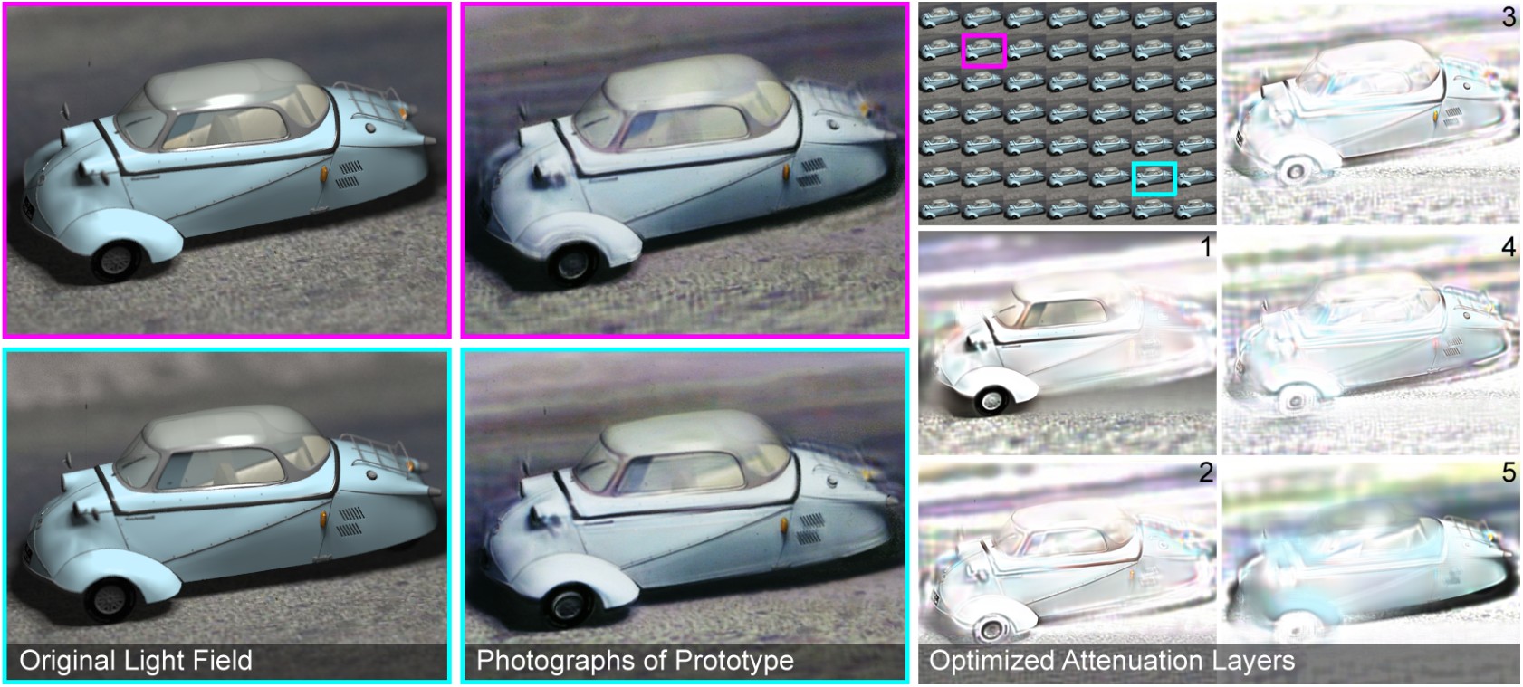
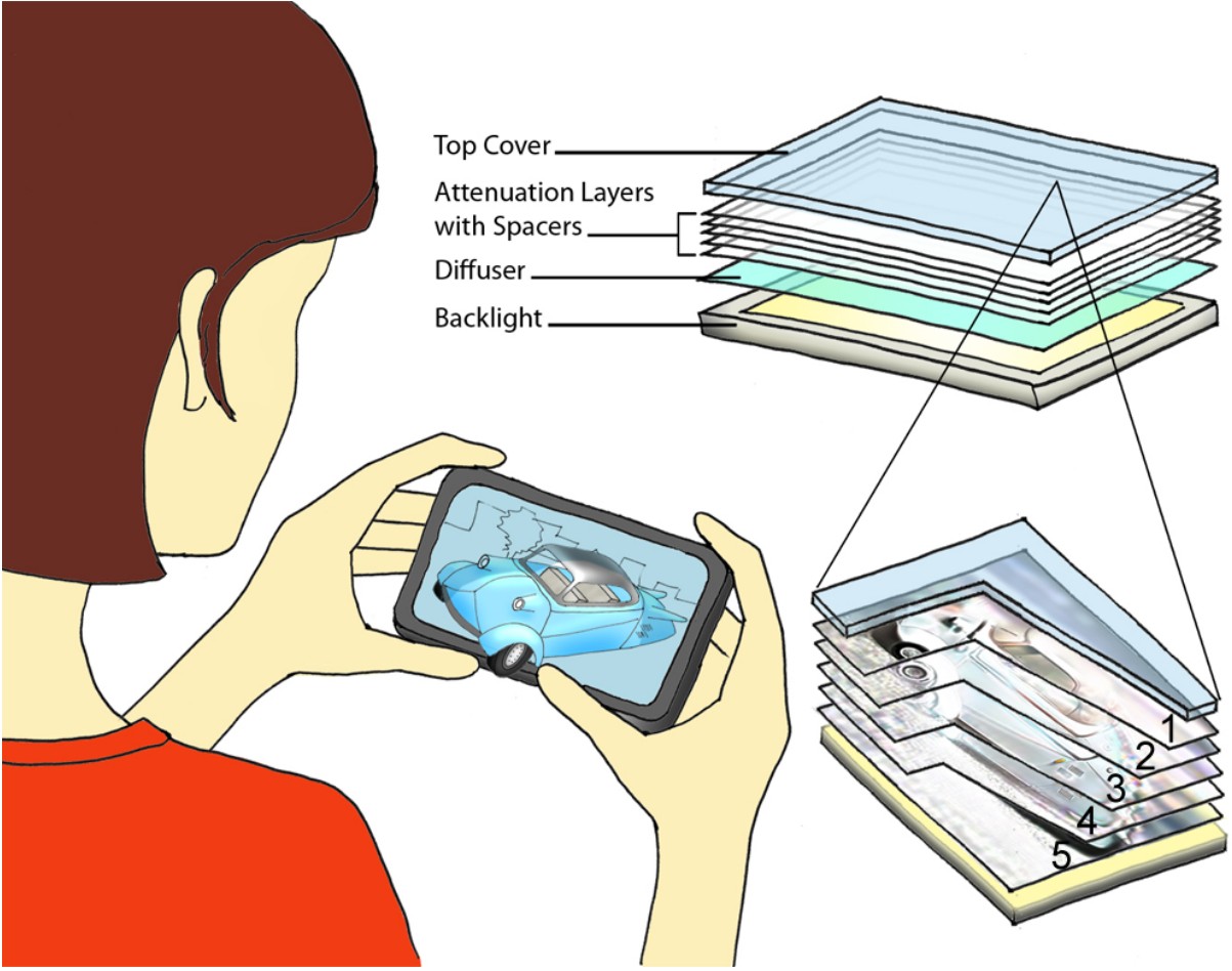
A stack of spatial light modulators (e.g., printed masks) recreates a target light field (here for a car) when illuminated by a backlight.
Low-cost prototype with uniform LCD backlight.
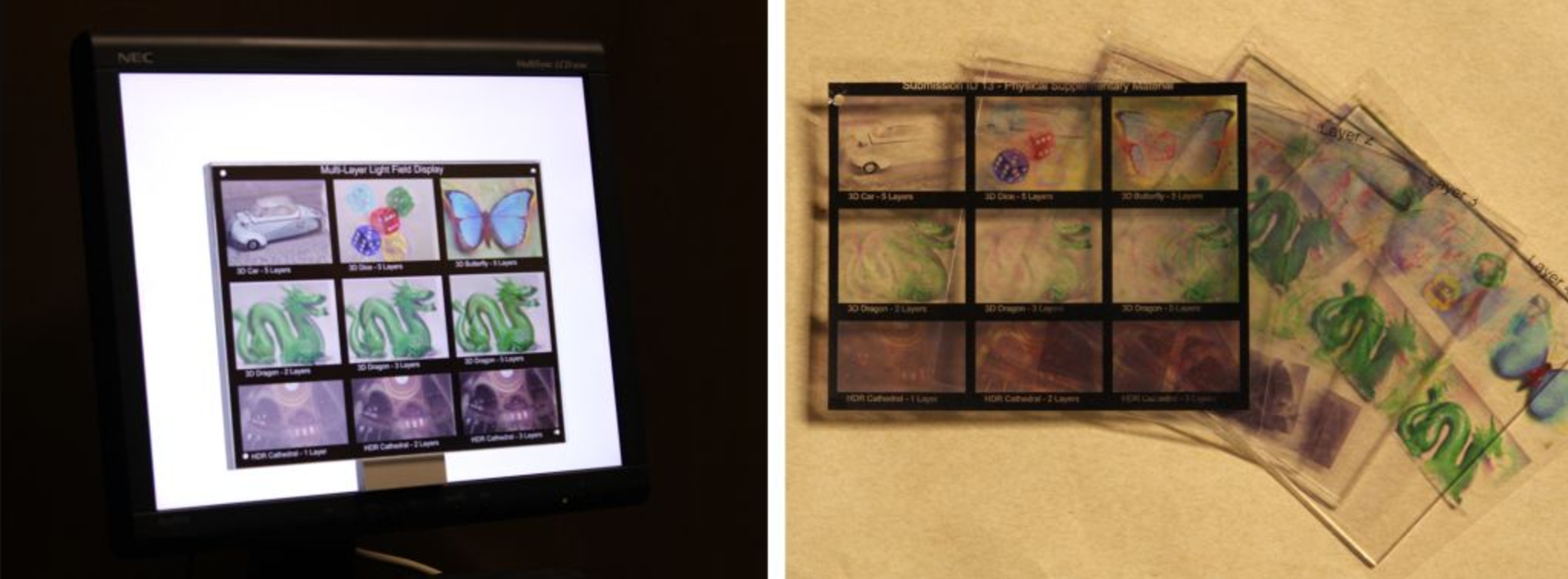
Prototype multi-layer display. (Left) We fabricate a multi-layer display by separating transparencies with acrylic sheets and back-illuminating with a light box (e.g., an LCD panel). (Right) Printed transparencies and acrylic layers.
Benefits of multi-layer displays. We enable sharper, brighter images than existing automultiscopic displays, but require additional layers and possibly thicker enclosures. *Flip animations, with uncorrelated multi-view imagery, are handled by enforcing parallax-barrier-like downsampling, described in Section 7.1 in the paper.
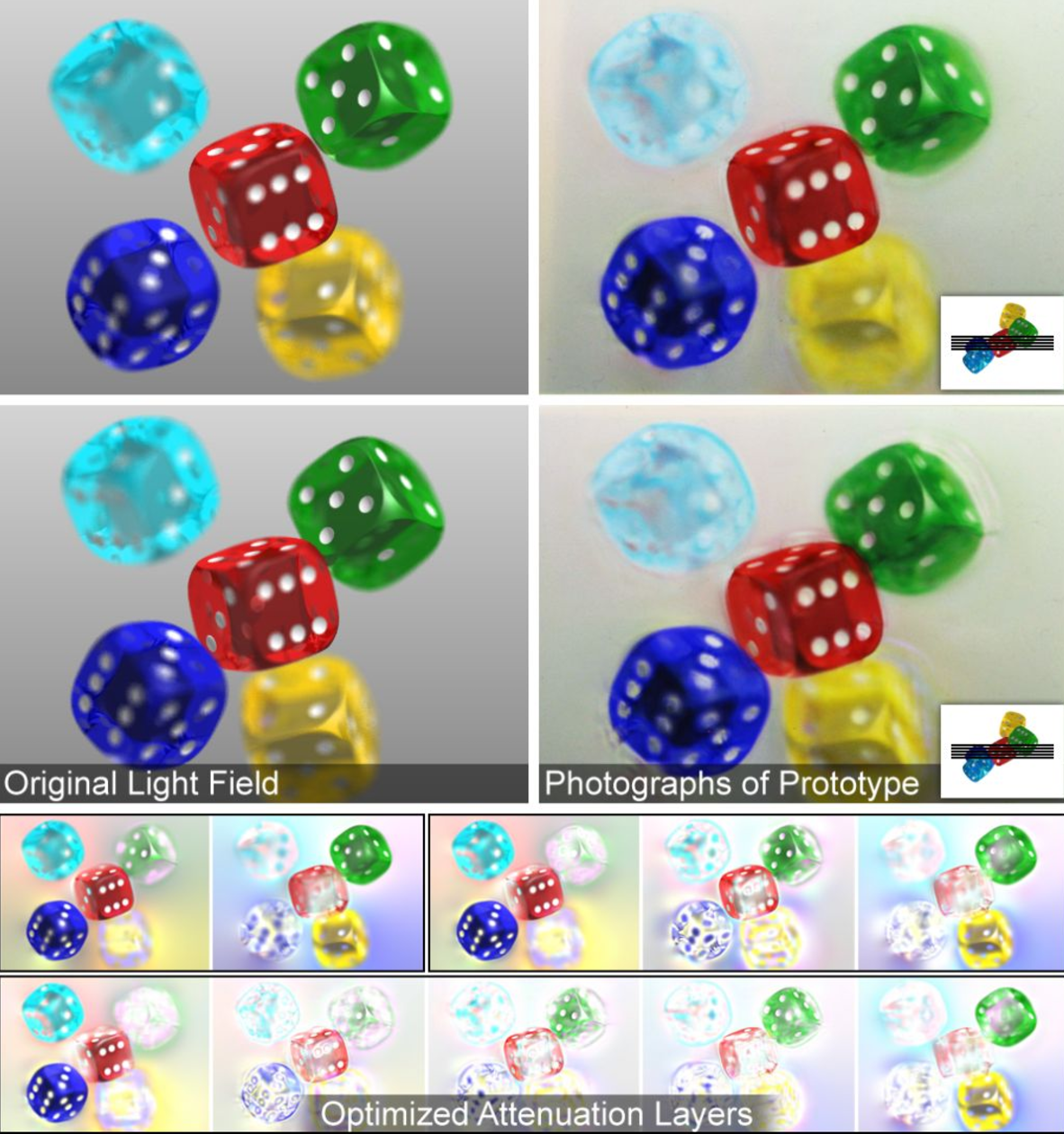
Multi-layer 3D display. The “dice” scene is rendered for vantage points to the right and left of the display, shown at the top and bottom of the left column, respectively. Corresponding views of the five-layer prototype (see Figure 2) are compared to the right. Inset figures denote the position of layers relative to the scene. Unlike conventional additive volumetric displays, both transparency and occlusion are accurately depicted, allowing for faithful representation of motion parallax for opaque objects. (Bottom) Clockwise from the upper left are two, three, and five layer decompositions, ordered from the front to the back of the display. All layers are uniformly-spaced and span the same total display thickness.
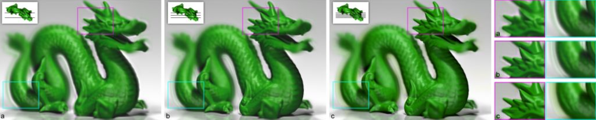
Influence of multi-layer depth of field on reconstruction artifacts. Shown from left to right are reconstructions of the “dragon” scene, using two, three, and five layers, seen when viewing directly in front. Magnified regions are compared on the right. The magenta region, located on the head and inside the display, is rendered with increasing resolution as additional layers are incorporated. The cyan region, located on the tail and behind the display, exhibits noticeable halo artifacts, similar to the dice in Figure 3. As described in Section 4.2 in the paper, the upper bound on depth of field for multi-layer displays indicates spatial resolution is inversely proportion to scene depth. Since high spatial frequencies are required to depict the tail edge, artifacts result without proper prefiltering. In this example, an approximation of the prefilter in Equation 17 (see paper) is applied assuming a five-layer decomposition, allowing artifacts to persist in the two-layer and three-layer decompositions.
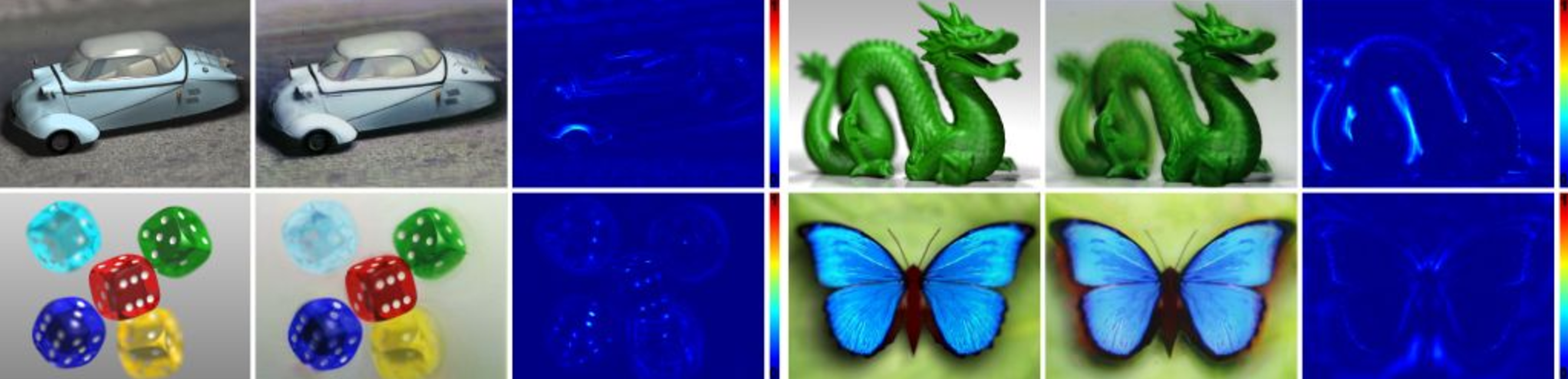
Multi-layer display performance. For each scene from left to right, a direct view of the target light field is compared to a prototype photograph and the absolute error between simulated and target views. Due to proper prefiltering, artifacts are evenly distributed in depth, occurring mostly near high-contrast edges (e.g., dragon silhouette and car fender). Note the specular highlight on the car roof is preserved, with reduced contrast, together with translucency of the windows. Additional results are included in the supplementary material and video.
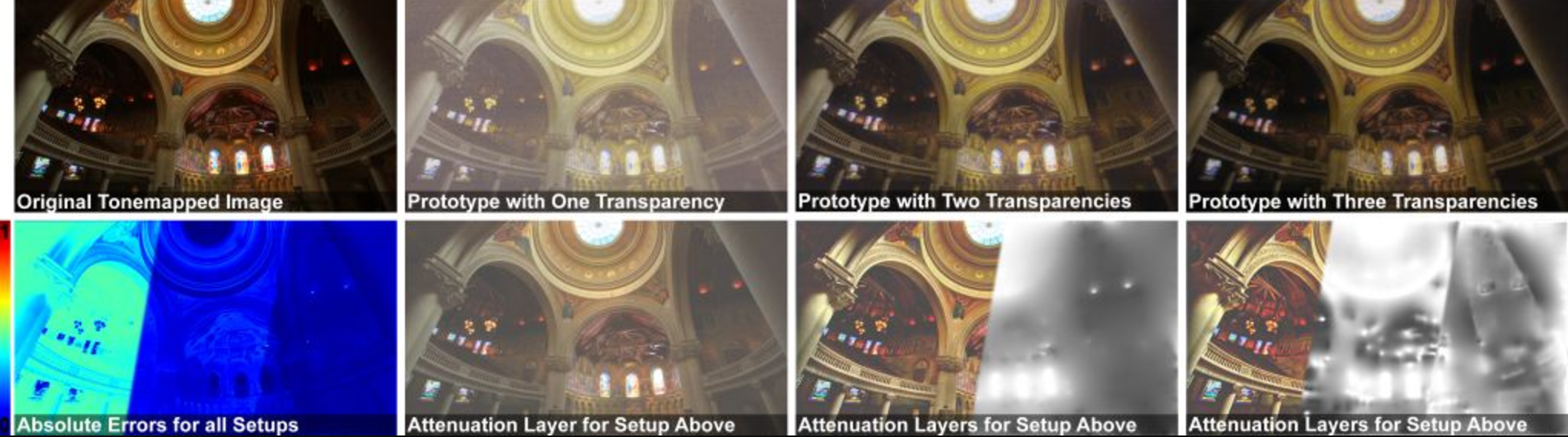
Multi-layer, parallax-free HDR image display. The target HDR image is shown, with tone mapping, on the upper left. Photographs of a multi-layer HDR display prototype, incorporating one, two, and three layers (each with a contrast of 3.3:1), are shown along the upper row; note how image contrast is improved by applying our tomographic image synthesis method together with multiple, physically-disjoint attenuation layers. The absolute errors between the simulated reconstructions and the target image are shown on the bottom left.
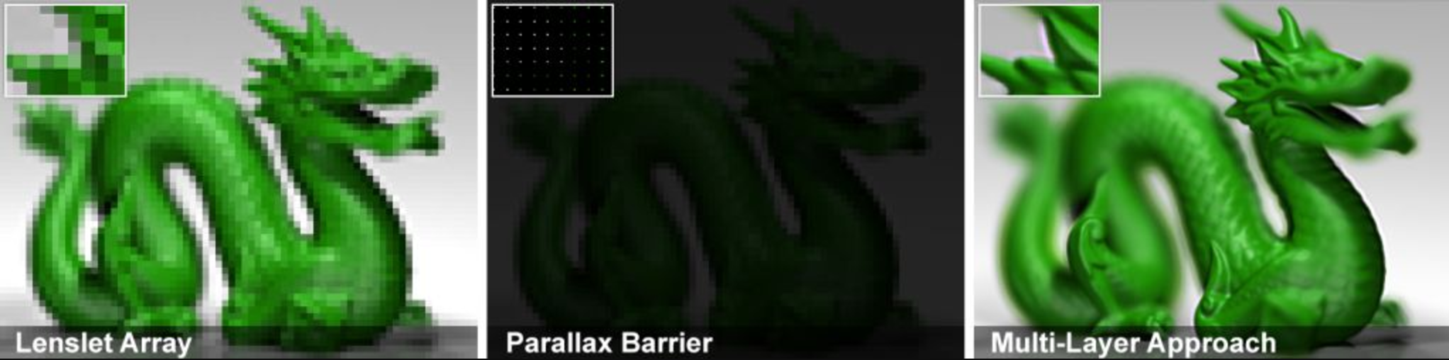
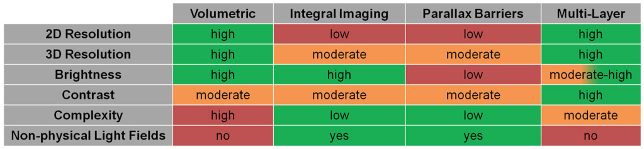
Benefits of multi-layer automultiscopic displays. Simulated views of the “dragon” are shown, from left to right, using integral imaging, parallax barriers, and our multi-layer approach. Display parameters are selected to allow 7×7 views, leading to a similar reduction in resolution for conventional methods. Compared to parallax barriers, our approach is 49 times brighter and exceeds the resolution of both methods by a similar factor.
Acknowledgments
We thank the reviewers for their insightful feedback and recognize the support of members of the Imager and Camera Culture groups at the University of British Columbia and the MIT Media Lab, respectively. We also thank Dolby and Samsung Electronics for their sponsorships and David Roodnick for helping to build the prototypes. Gordon Wetzstein was supported by a UBC Four Year Fellowship. Wolfgang Heidrich was supported under the Dolby Research Chair in Computer Science at UBC. Ramesh Raskar was supported by an Alfred P. Sloan Research Fellowship.